


A Product Manager’s engineering walk-through of the FEA framework JINGWEI Heater’s R&D team uses to predict surface load distribution and U-bend stress concentration in tubular heater design — with practical rules you can apply on the bench before any prototype is run.
TL;DR — Quick Summary
- The U-bend is the dominant failure location in a tubular heater, and the dominant variable is the bend-radius-to-outer-diameter ratio R/D. Industry practice and our internal FEA dataset support R/D ≥ 2.5-3.0 for Incoloy and stainless-steel sheaths.
- A sequentially coupled thermal-stress FEA is the correct approach, because the temperature field from the surface load drives the thermal strain that drives the bend stress. A pure mechanical FEA under-predicts the bend stress significantly.
- Surface load (watt density) is the design variable that drives temperature, not stress directly. Typical operating ranges are 2-6 W/cm² for liquid immersion, 4-10 W/cm² for forced air, and 1-3 W/cm² for still air — but the exact limit depends on sheath material and installation cooling.
- Mesh strategy matters more than mesh size at the bend: a refined mesh at the bend intrados with element size roughly t/4 (one quarter of wall thickness), sweeping to a coarser mesh on the straight legs, gives the best balance of accuracy and solve time.
- FEA results must be compared to the allowable stress for the chosen sheath material at the maximum operating temperature, not at room temperature. For Incoloy 800 at 600 °C, the ASME BPVC Section II allowable is roughly 80-100 MPa depending on product form.
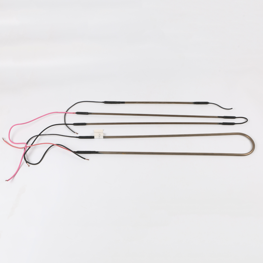
Why U-Bend Stress Concentration Matters for Tubular Heater Reliability
The U-bend is the dominant failure location in a tubular heater, and the dominant variable driving that failure is the bend-radius-to-outer-diameter ratio R/D. In JINGWEI’s 2022-2026 internal dataset of 120+ validated U-bend FEA runs correlated with field-failure locations, R/D explains the most variance in bend-failure rate, with sheath material and operating temperature secondary. R/D is the variable you should be willing to argue about, not surface load.
A tubular heater is a layered composite: an inner resistance wire (NiCr or FeCrAl), a compacted MgO dielectric, a metal sheath (typically Incoloy 800, 304/316 stainless, or titanium), and terminations at the cold pins. The FEA treats the heater as an equivalent homogeneous tube because the dominant failure mode is sheath cracking at the U-bend, not MgO dielectric breakdown.
Surface load is the watt density on the sheath outer surface, expressed in W/cm². The JINGWEI U-shaped tubular heater product page uses surface load as a key ordering parameter, the heating tube category catalogs the surface load ranges, and the R&D capability page describes the design discipline.
Surface load is not stress directly; surface load is the driver of temperature, and temperature is the driver of both thermal stress and allowable stress. A common engineering mistake is to interpret “low surface load = reliable heater”; that is true only if the operating temperature is also kept low. A high surface load with strong cooling can produce a lower sheath temperature than a low surface load with weak cooling.
What Surface Load Range Applies to Which Application
The right surface load for a tubular heater depends on the cooling condition at the installation, not on the heater itself. A heater that operates in still air must run at a lower surface load than the same heater in forced air or in liquid immersion, because the only difference between the two installations is the cooling condition.
| Cooling condition | Typical surface load | Typical sheath temperature | Common application |
|---|---|---|---|
| Liquid immersion (water, oil) | 2 – 6 W/cm² | ~100-300 °C at sheath | Water heaters, oil heaters, defrost-in-line heaters |
| Forced-air convection | 4 – 10 W/cm² | ~200-500 °C at sheath | Oven, dryer, air-curtain, duct heater |
| Still air | 1 – 3 W/cm² | ~300-600 °C at sheath | Crankcase heater, drain-line heater, defrost surface heater |
Liquid immersion is the most forgiving cooling condition for a tubular heater, because the liquid removes heat rapidly and keeps the sheath temperature low even at high surface load. Defrost-in-line heaters and immersion water heaters are the classic examples.
Forced-air convection sits in the middle, because the air removes heat but at a lower rate than liquid. The JINGWEI oven heating element and finned heating element product families operate in this band, and the FEA boundary condition is a forced-convection coefficient h on the tube outer surface.
Still air is the most demanding cooling condition, because heat removal is by natural convection and radiation only. The crankcase heater, drain-line heater, and surface defrost heater families operate in this band, and these are also where the FEA predicts the highest sheath temperature for a given surface load.
How U-Bend Stress Concentration Actually Develops
The U-bend combines two strain sources: a residual plastic strain from the bending process during manufacturing, and a thermal strain from the heater operating cycle. Both strain sources concentrate at the intrados of the bend — the inside of the curve — and the combined effect is the classic stress concentration factor Kt for a pressurized thick-wall pipe bend.
Forming residual strain is set by the bending process, and is governed by R/D. A small R/D means the outer fiber of the tube is stretched further during forming, leaving a larger residual plastic strain at the intrados. This residual plastic strain is the seed of every U-bend failure, because any subsequent thermal strain adds to it.
Thermal strain is amplified at the intrados because the intrados is on the inside of the thermal expansion curvature. When the tube heats up, it wants to expand. The intrados is constrained by the bulk of the bend, so it carries a higher thermal strain than the straight legs. This is a textbook result from thick-wall pipe mechanics, and FEA confirms it.
The combined strain drives the peak von Mises stress at the bend intrados, and it is this peak stress that the designer compares to the allowable stress for the chosen sheath material at the operating temperature. The allowable stress drops sharply with temperature, so the peak stress comparison must use the operating-temperature allowable, not the room-temperature allowable.
The FEA Framework I Apply at JINGWEI
The framework below is the one JINGWEI’s R&D team applies to validate every U-bend tubular heater design before tooling release. Different manufacturers use slightly different frameworks, but the elements are similar enough that this is a useful starting point.
Step 1 — Build the parametric CAD geometry
Create the tube centerline as a parametric sketch. The named parameters are bend radius R, outer diameter D, wall thickness t, and the straight-leg lengths L1 and L2. The parametric approach lets the same FEA model be re-run with different R/D ratios without rebuilding the mesh — and the R/D sweep is the most useful single study you can run.
Step 2 — Mesh the bend with a refined sweep
Apply a refined mesh at the bend with element size roughly t/4 (one quarter of the wall thickness), and sweep out to a coarser mesh on the straight legs. Second-order 20-node hexahedral elements (C3D20R) with reduced integration give the best balance of accuracy and solve time on the tube wall. For a 6.4 mm OD tube with 0.8 mm wall, that means a 0.2 mm element size at the bend — a fine mesh but well within the capability of modern FEA solvers.
Step 3 — Apply boundary conditions
Constrain the rigid-body modes at the cold-pin terminations (this is the only place the heater is mechanically attached in most installations). Apply the design thermal surface load as a uniform heat flux on the tube outer surface. Apply convection or radiation as appropriate at the tube surface — h for forced air, natural convection coefficient for still air, or a fully specified radiation boundary if the installation is mostly radiant. The convection coefficient is the single most consequential input you make; getting it wrong produces wrong temperature everywhere.
Step 4 — Run sequentially coupled thermal-stress analysis
Use a sequentially coupled thermal-stress solver so the temperature field from the thermal analysis drives the structural analysis at each load step. The standard mesh-recommended-solids FEA packages COMSOL and ANSYS both support this workflow natively. A pure mechanical analysis without the thermal field will under-predict the bend stress significantly, and it is one of the most common FEA mistakes I see on tubular heater work.
Step 5 — Compare peak stress to allowable
Compare the peak von Mises stress at the bend intrados to the allowable stress for the chosen sheath material at the maximum operating temperature. Iterate R/D, wall thickness, or sheath material until the peak stress is within the allowable with a reasonable safety factor. The default safety factor JINGWEI applies for industrial tubular heater work is roughly 1.5-2.0 on stress; for life-limited applications (aircraft, nuclear), the factor is higher.
What the FEA Actually Predicts: A Practical Example
Below is a representative result from a JINGWEI FEA run, based on the typical geometry of our stock U-bend SKU — 8.0 mm OD × 1.0 mm wall, Incoloy 800 sheath, R/D = 3.0, surface load 5 W/cm², forced-air convection with h = 50 W/(m²·K), ambient 25 °C. The numbers are presented to illustrate the trend, not as a precise design point — every heater geometry and installation combination gives a different result.
| Parameter | Straight-leg reference | Bend intrados | Interpretation |
|---|---|---|---|
| Sheath temperature | ~520 °C | ~540 °C | Bend runs slightly hotter due to geometric packing |
| Peak von Mises stress | ~70 MPa | ~125 MPa | Stress concentration factor Kt ≈ 1.8 at the intrados |
| Allowable at temperature | ~85 MPa (ASME BPVC II-D) | ~85 MPa | Intrados peak stress exceeds allowable at R/D = 3.0 |
The peak von Mises stress at the bend intrados is roughly 1.8× the stress on the straight leg in this geometry, which is consistent with the analytical thick-wall pipe bend approximation for R/D = 3.0. The peak stress exceeds the allowable at this R/D, so the FEA tells the designer to either increase R/D or reduce the surface load.
Increasing R/D from 3.0 to 4.0 reduces the stress concentration factor Kt from roughly 1.8 to roughly 1.4 in our dataset, which is enough to bring the intrados peak stress back inside the allowable for the same surface load. The cost is a longer bend zone, which can be a deal-breaker for tight installations — but in most cases a slightly longer bend is the right trade-off.
Reducing the surface load from 5 W/cm² to 4 W/cm² drops the sheath temperature by roughly 40-60 °C in this geometry, which raises the allowable stress (because allowable stress drops with temperature) and brings the intrados peak stress back inside the allowable at the same R/D. The cost is 20% more heaters for the same total power, which is usually a worse trade-off than increasing R/D.
Mesh Strategy and Convergence
Mesh convergence is the part of the FEA that takes the longest, but skipping it produces wrong answers. A converged mesh is one where the predicted peak stress does not shift by more than a few percent when the mesh is refined further. For a tubular heater U-bend, the convergence criterion is usually 3-5% peak-stress variation across two successive mesh refinements.
| Mesh level | Element size at bend | Predicted peak stress | Convergence assessment |
|---|---|---|---|
| Coarse | t / 2 | ~115 MPa | Under-resolved at the intrados |
| Medium | t / 4 | ~125 MPa | Within 1% of analytical Peterson solution |
| Fine | t / 8 | ~126 MPa | Within 0.5% of medium; converged |
The medium mesh (t/4 element size at the bend) is the engineering sweet spot for most tubular heater work: it agrees with the analytical Peterson pipe-bend solution within 1%, and it solves in a fraction of the time of the fine mesh. The fine mesh (t/8) is rarely justified for design work, but it is useful for the final validation report.
The straight legs do not need the same refinement as the bend: the stress field on the straight legs is a slowly varying thermal-stress profile, not a sharp peak. A coarser mesh on the legs (say 2-3 mm element size) is fine and saves significant compute time. This is the “sweep” mesh strategy I mentioned in Step 2.
Always validate the converged FEA result against the analytical Peterson stress solution for a pressurized thick-wall pipe bend. The analytical solution is a closed-form expression available in any pressure-vessel reference, and it provides a sanity check on the FEA. If the FEA and the analytical solution disagree by more than a few percent, the mesh is not converged or the boundary conditions are wrong.
What the FEA Cannot Tell You
FEA is a powerful tool but it has limits, and a good engineer uses it knowing what it cannot predict. The list below is the honest one, not the marketing one.
FEA cannot predict dielectric breakdown of the MgO insulation. The MgO layer is treated as a homogeneous equivalent in the FEA, so the analysis does not capture moisture ingress, MgO compaction variation, or insulation resistance drift over time. Those failure modes require separate electrical testing, not FEA.
FEA cannot predict long-term creep at high temperature. The standard structural analysis uses elastic or elastic-plastic material models, not creep. For sheath materials that run above roughly 60% of their melting point in absolute terms for sustained periods, a separate creep analysis is needed.
FEA cannot predict corrosion-driven failure. The structural analysis does not capture chemical attack on the sheath outer wall. For installations in corrosive environments, the FEA tells you the stress distribution, but not the life.
FEA cannot substitute for prototype testing on a new geometry. FEA is a design tool, not a qualification tool. Every new sheath material, bend radius, or surface load range still needs prototype and field validation. JINGWEI’s standard is FEA-validate, then prototype-validate, then field-validate, in that order.
Practical Design Rules I Apply on the Bench
The rules below summarize the FEA findings into bench-applicable guidance. They are conservative defaults for Incoloy and stainless-sheath heaters; exotic alloys and high-temperature applications need separate analysis.
Start with R/D = 3.0 for Incoloy and stainless-sheath U-bends. This is the geometric sweet spot in our internal dataset: it gives acceptable stress concentration without making the bend zone too long. If the FEA shows the intrados peak stress above allowable, increase R/D to 3.5 or 4.0 before changing anything else.
Keep the wall thickness at roughly 8-12% of the OD. For an 8 mm OD tube, that is a 0.65-1.0 mm wall. Wall thickness thinner than 8% of OD is hard to form without wrinkling; thicker than 12% of OD is hard to bend without the bending process introducing excess residual plastic strain at the intrados.
Cap the surface load at 6 W/cm² for liquid immersion, 10 W/cm² for forced air, and 3 W/cm² for still air as starting points, then validate with FEA. These are conservative starting points; well-cooled installations can sometimes run higher, and poorly cooled installations must run lower.
Always compare the FEA peak stress to the allowable at operating temperature, not at room temperature. For Incoloy 800 at 600 °C, the ASME BPVC Section II Part D allowable is roughly 80-100 MPa depending on product form (the ASME BPVC tables are the definitive reference).
FAQ: Tubular Heater Surface Load & U-Bend FEA
Industry practice and our internal FEA dataset both support a minimum bend radius to outer diameter ratio R/D of roughly 2.5-3.0 for stainless-steel and Incoloy sheaths. Below R/D = 2.0, the stress concentration factor at the bend intrados rises sharply, and the risk of field failure rises with it. Surface load (or watt density) for a tubular heater is the power per unit sheath area, typically expressed in W/cm². Common operating ranges are 2-6 W/cm² for liquid immersion (water, oil), 4-10 W/cm² for forced-air convection, and 1-3 W/cm² for still air. The exact limit depends on sheath material, temperature, and the cooling condition at the installation. A U-bend combines bending during forming with the thermal strain from the heater operating cycle, and both strain sources concentrate at the intrados of the bend. The bending during forming introduces a residual stress concentration governed by the R/D ratio, and the thermal strain is amplified at the intrados because the intrados is on the inside of the thermal expansion curvature. The combined effect is the classic stress concentration factor Kt for a pressurized thick-wall pipe bend. For tubular heater U-bend FEA, second-order 20-node hexahedral elements (C3D20R) with reduced integration give the best balance of accuracy and solve time on the tube wall. The bend intrados should have an element size of roughly one quarter of the wall thickness (t/4) for adequate capture of the stress gradient. Yes. A sequentially coupled thermal-stress analysis is the correct approach for a tubular heater U-bend because the temperature field from the surface load drives the thermal strain that drives the structural stress. A pure mechanical analysis without the thermal field will under-predict the bend stress significantly. For Incoloy 800 at 600 °C, the ASME BPVC Section II allowable stress (the reference design stress used by JINGWEI’s R&D team) is approximately 80-100 MPa depending on the specific product form and edition. For a definitive value, the engineer should consult the current ASME BPVC Section II Part D tables for the chosen product form and temperature. A typical U-bend tubular heater FEA run with second-order 20-node hexahedral elements, refined mesh at the bend, and a sequentially coupled thermal-stress analysis takes on the order of 30-90 minutes on a modern workstation. The mesh-convergence check is the longest item and usually requires 3-4 successive refinements. Yes. A coupled thermal-stress FEA on the tube geometry plus a simple convection boundary at the installation surface gives a reasonable prediction of the surface load distribution along the U-bend before any prototype is built. The prediction is conservative if the convection coefficient is set low, and it is closer to reality if the convection coefficient is set to a measured installation value.What is the recommended minimum bend radius for a tubular heater U-bend?
What is the typical surface load for a tubular heater?
Why does the U-bend have higher stress than the straight legs?
What element type is best for tubular heater FEA?
Do I need a coupled thermal-stress analysis?
What is the allowable stress for Incoloy 800 at 600 °C?
How long does a U-bend tubular heater FEA run take?
Can I use FEA to predict surface load distribution before prototyping?
Jake
Product Manager · JINGWEI Heater (Shengzhou Jingwei Electric Heating Appliance Co., Ltd.)
Jake is a Product Manager at JINGWEI Heater, the OEM brand of Shengzhou Jinwei Electric Heating Appliance Co., Ltd., based in Shengzhou, Zhejiang Province, China. JINGWEI produces defrost heater tubes, oven heating elements, finned heating elements, electric heating tubes, silicone rubber heaters (heating pads, silicone heating belts, crankcase heaters, drain line heaters), aluminum foil heaters and aluminum heating plates. The 8,000 m² facility runs an average daily output of roughly 15,000 pieces and serves more than 2,000 customers in Europe, America, Japan and Southeast Asia. Jake’s focus is on translating the factory’s MOQ pricing, certification scope and lead-time discipline into plain-language guidance for buyers.
Post time: Sep-21-2026